Arduino
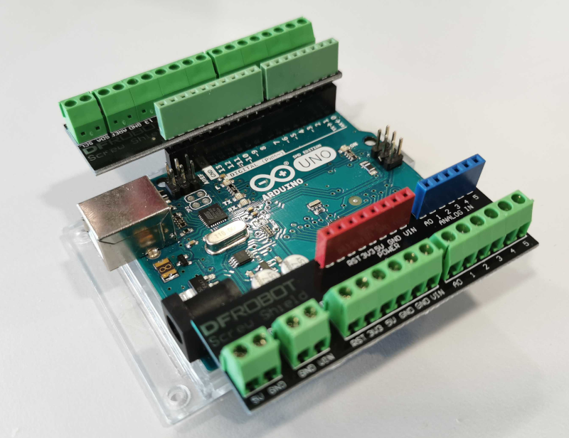
This board allows you to control GPIO pins and analogue pins. More specifically, it's an Arduino Uno.

Headers
We have supplied 2 screw terminal headers for your Arduino, allowing you to easily and securely attach your sensors.
The reset button
The small button next to the USB socket allows you to instantly reboot the Arduino in case it isn't working. This isn't a guaranteed fix, but may solve some problems.
GPIO Pins
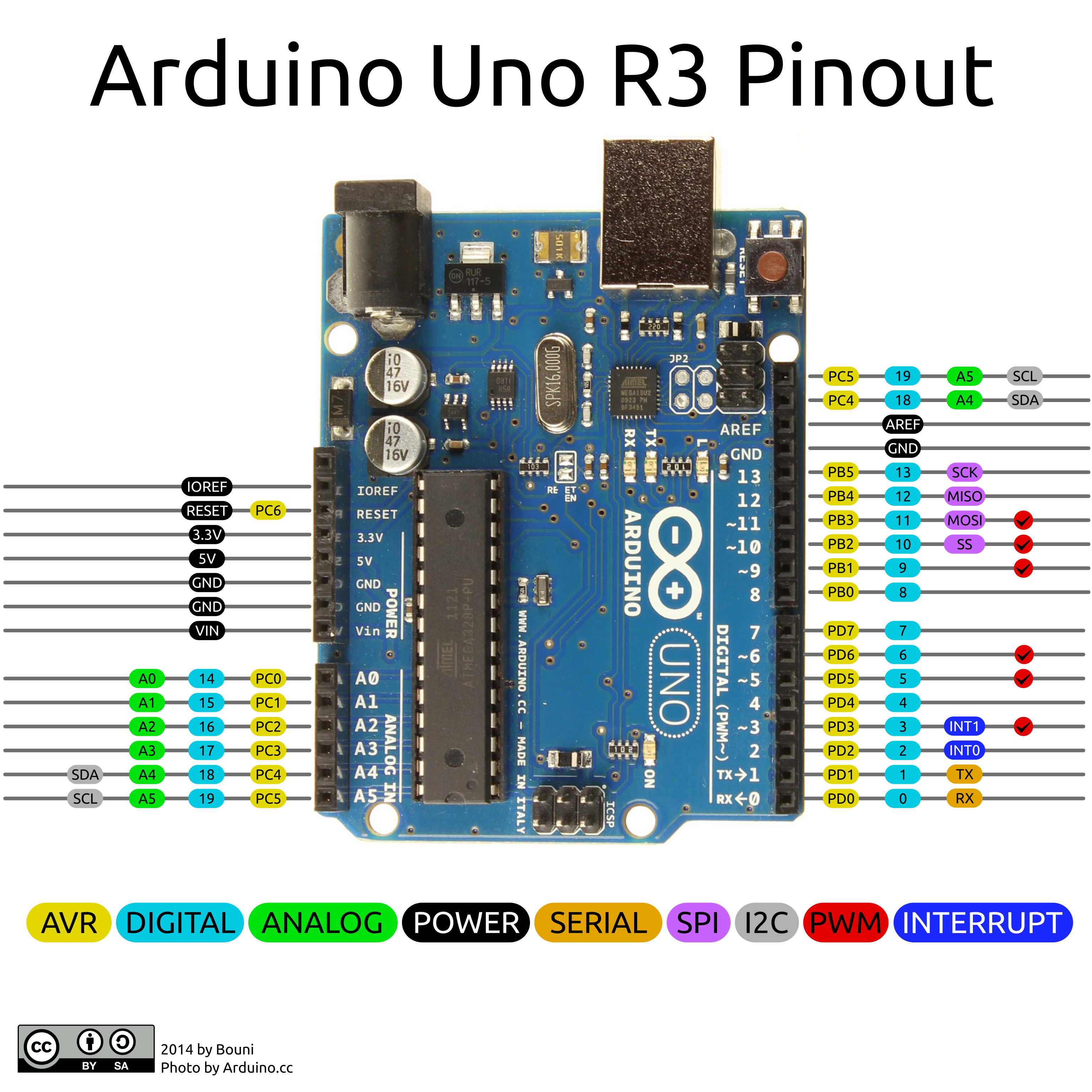
The Arduino allows you to connect your kit to your own electronics. It has fourteen digital I/O pins, and six analogue input pins. The analogue pins can read an analogue signal from 0 to 5V and the digital pins can receive or send digital signals at 0V & 5V. The board also has a couple of ground pins, as well as some pins fixed at 3.3V and 5V output to supply power to your sensors.

Ultrasound Sensors
Ultrasound sensors are a useful way of measuring distance. Ultrasound sensors communicate with the kit using two wires. A signal is sent to the sensor on the trigger pin, and the length of a response pulse on the echo pin can be used to calculate the distance.
Ultrasound should only be considered accurate up to around two metres, beyond which the signal can become distorted and produce erroneous results.
The sensor has four pin connections: ground, 5V (sometimes labelled vcc), trigger and echo. Most ultrasound sensors will label which pin is which. The ground and 5V should be wired to the ground and 5V pins of the Arduino respectively. The trigger and echo pins should be attached to two different digital IO pins. Take note of these two pins, you'll need them to use the sensor.
If the sensor always returns a distance of zero, it might mean the trigger and echo pins are connected the wrong way! Either change the pin numbers in the code, or swap the connections.
Designs
The schematic diagrams for the Arduino is below, as well as the source code of the firmware on the Arduino. You do not need this information to use the board but it may be of interest to some people.